Make Sure Your Fire and Gas Detectors Are in the Right Places
Your flame and gas detectors may be operational and correctly calibrated—but will they detect a real gas leak or fire early enough?
Detector effectiveness depends not only on the equipment itself, but also on its location, mounting height, orientation and surrounding conditions. Changes to machinery, ventilation, production processes or facility layouts may create new detection blind spots.
A detector installed in the right place several years ago may no longer provide suitable coverage today.
Quick Tip: Changes to your facility, processes or ventilation can affect detector coverage. Regular flame and gas mapping helps identify blind spots and ensure detectors remain positioned for effective early warning.
Key Takeaways
- A working detector may still miss a hazard if gas or flame cannot reach its detection area.
- New equipment, ventilation or layout changes may reduce the effectiveness of existing detector locations.
- Flame and gas mapping identifies coverage gaps and shows where detectors should be repositioned, replaced or added.
Why Correct Gas Detector Placement Matters
A gas detector can only provide an early warning when hazardous gas reaches its sensor. If a detector is too far from a potential leak source, installed at an unsuitable height, affected by ventilation or separated from the hazard by equipment and structures, detection may be delayed—or the gas may not reach that detector. Similarly, a flame detector may not detect a developing fire if machinery, pipes, walls or other structures block its field of view.
Incorrect placement may result in:
Undetected Hazards
Gas leaks or fires may go undetected, leaving personnel, equipment and facilities exposed without warning.
Delayed Response
Late detection delays alarms, evacuation and emergency action, allowing an incident to become more severe.
Coverage Gaps
High-risk areas remain unprotected even when the system appears to be operating normally.
Unnecessary Costs
Poor placement may lead to additional detectors, rewiring, relocation and higher calibration and maintenance costs.
Effective gas detector placement should not be based only on general rules or previous installations. Every facility has different hazards, layouts and environmental conditions.
Guidance for Flame and Gas Detector Placement
There is no single detector location that is correct for every facility. Effective placement must be based on the specific hazard, the facility layout and how gas or flame may be detected under real operating conditions.
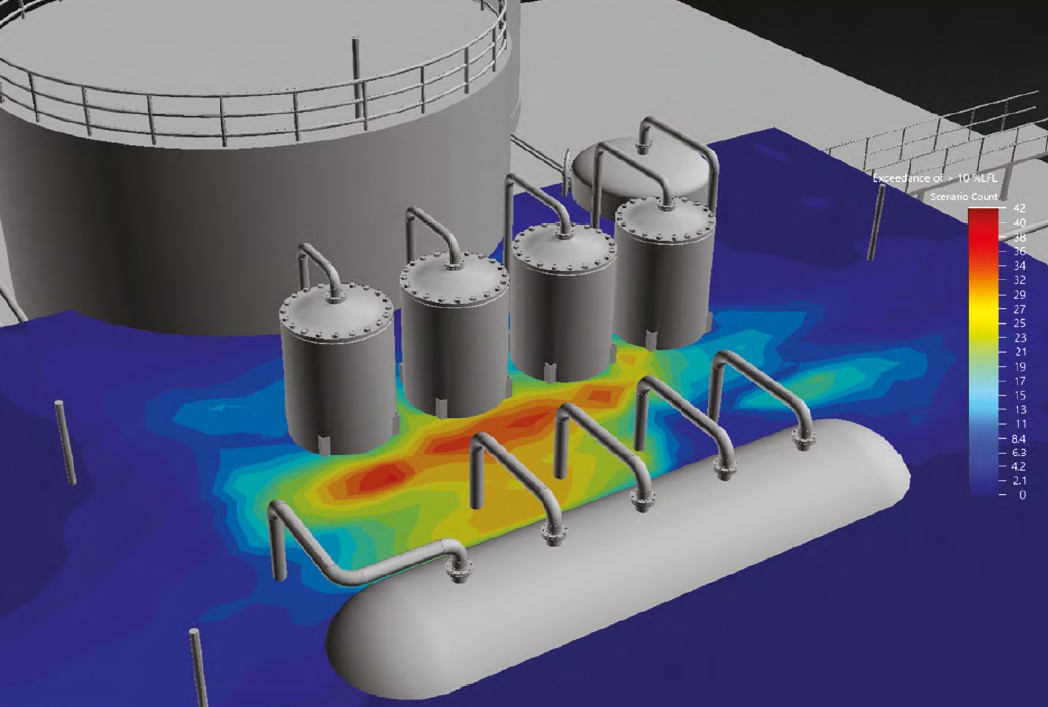
Gas Detector Placement
Fixed gas detectors should be positioned near credible release sources and along the expected path of gas movement. Placement decisions should consider:
The type of gas and its expected behaviour after release
Potential leak points, such as pumps, valves, flanges, pipework and storage equipment
Ventilation, extraction systems, wind direction and airflow patterns
Enclosed spaces, low points, pits, trenches and areas where gas may accumulate
Equipment, walls and structures that may obstruct gas movement
Personnel exposure areas and the required alarm response time
For example, a detector should not be placed solely because it is close to electrical power or easy to access for maintenance. It must be located where a release is most likely to reach the sensor quickly enough to provide meaningful warning.
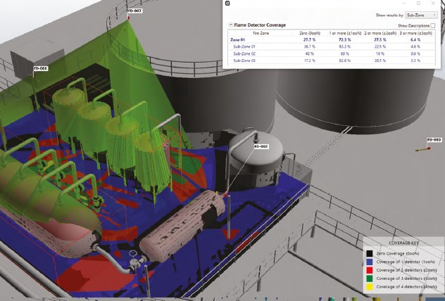
Fire Detector Placement
Flame detectors should be installed with a clear, unobstructed view of credible fire-risk areas. The placement should consider:
Likely ignition and fire locations
The type, size and fuel source of the fire that must be detected
The detector’s specified field of view and detection distance
Obstructions such as process equipment, pipework, tanks, walls, platforms and structural steel
Mounting height, orientation and viewing angle
Environmental conditions, including sunlight, hot surfaces, reflections, smoke, dust, steam and vibration
Whether multiple detectors are needed to cover separate areas or remove line-of-sight blind spots
A flame detector may be operational and correctly calibrated but still fail to detect a fire if the flame is outside its field of view or blocked by equipment. Whenever a facility layout changes, flame-detector viewing angles and coverage should be reviewed.
Review Your Existing Gas Detection Systems
Industrial environments rarely remain unchanged. Equipment is added, production lines are relocated, walls and platforms are constructed, and ventilation systems are modified. Each of these changes can alter how gas disperses through a space, and where the risk of fire or gas accumulation is most likely to occur. A detector layout that was appropriate at commissioning may no longer reflect the actual risk profile of the facility.
It is important to understand a critical distinction that is often overlooked: calibration confirms that a detector can respond to gas — it does not confirm that gas from an actual leak will reach the detector. A perfectly calibrated instrument positioned in the wrong location will still fail to provide meaningful protection.
Review Your Detector Layout When:
Equipment Added
New machinery or storage tanks are installed
Lines Relocated
Production lines or process areas are moved
Ventilation Changed
Ventilation or HVAC systems are modified
Structures Added
Walls, platforms or structures are installed
New Chemicals
New gases or hazardous substances are introduced
Risk Assessments Updated
Safety requirements or risk assessments are revised
Layout, airflow and process changes can silently create new detection gaps—without triggering any alarm or calibration fault in your existing system. Regular reviews are an essential part of maintaining effective coverage.
Improve Coverage Before Adding More Detectors
A coverage gap does not automatically mean you need more detectors. The issue may be the detector’s location, mounting height, viewing angle or technology.
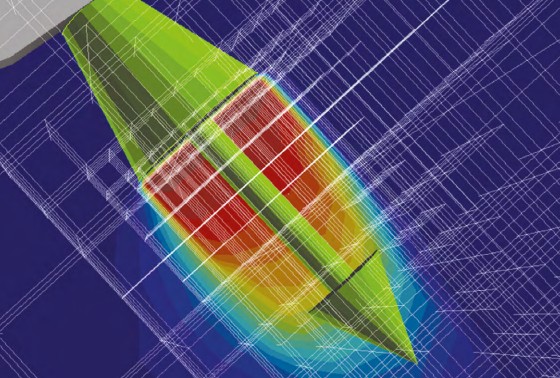
Flame and gas mapping can evaluates how gas may spread after a leak and whether flame detectors have a clear view of potential fire-risk areas. It considers possible leak and fire locations, gas behaviour, airflow, equipment layout, detection distance and structural obstructions.
The results show which areas are covered, identify possible blind spots and help determine whether detectors should be:
- Repositioned or reoriented
- Installed at a different height
- Replaced with more suitable technology
- Added only where genuine gaps remain
Detector Placement: Without Mapping vs. Risk-Based Mapping
| Approach | Without Mapping | With Risk-Based Mapping |
|---|---|---|
| Detector placement | Based mainly on general rules or past layout | Evaluated against current hazards, airflow and coverage |
| Coverage gaps | May remain unseen | Visualised and documented |
| System changes | Often addressed reactively | Reviewed when layout or process changes |
| Detector quantity | Additional units may be added by default | Existing units are optimised before new units are added |
| Lifecycle cost | Possible unnecessary installation and maintenance | More informed use of detector resources |
| Safety decisions | Depend more heavily on assumptions | Supported by coverage analysis and 3D visualisation |
The goal of risk-based mapping is to build a gas detection system that provides effective coverage for actual facility risks — not simply to accumulate more hardware. This distinction has meaningful implications for both safety outcomes and the long-term cost of operating a fixed gas detection system.
Dräger Flame & Gas Mapping
Dräger Flame & Gas Mapping provides a structured, risk-based approach to evaluating flame and gas detector coverage. It considers your facility’s actual hazards, equipment layout, operating conditions and existing detectors to support more reliable placement decisions.
The solution can be applied to new installations or used to assess and improve an existing flame and gas detection system.
Key Features
- Suitable for new and existing installations
- Risk-based and facility-specific assessment
- Visualisation of flame and gas detector coverage
- Identification of potential detection blind spots
- Review of detector quantity, location, height and orientation
- Consideration of gas behaviour, airflow and ventilation
- Assessment of flame-detector viewing angles and obstructions
- Optimisation of existing detectors before additional units are considered
- Recommendations for suitable detector technologies
- Clear documentation to support future reviews and facility changes
A structured four-step process ensures your detector coverage is evaluated thoroughly and recommendations are grounded in your facility’s actual conditions.
Identify Gaps
Locate potential coverage blind spots across the facility.
Visualise Coverage
Review existing detector positions and coverage areas.
Optimise Layout
Reduce unnecessary overlap and determine where repositioning helps.
Document Decisions
Support future safety assessments and facility changes with clear records.
Build a Gas Detection System Today
Dräger Flame & Gas Mapping provides a structured, risk-based way to evaluate coverage, identify gaps and make more informed detector-placement decisions. Whether you are reviewing an existing system, planning an expansion or simply cannot document why detectors are positioned where they are, a mapping study provides the evidence needed to act with confidence.
- Review : Assess your existing system against current facility conditions
- Map : Visualise coverage gaps using risk-based 3D analysis
- Optimise : Reposition, replace/ add detectors only where evidence supports it
- Document : Produce auditable records of coverage decisions for safety reviews
Frequently Asked Questions
The following questions address common points raised by EHS managers, safety engineers and facility managers when considering flame and gas detection reviews.
What is flame and gas mapping?
Flame and gas mapping is a risk-based assessment of whether detectors provide suitable coverage for identified hazards and facility conditions. It considers factors such as potential release sources, gas behaviour, equipment layout, airflow, detector technology and flame-detector fields of view. The results help show where coverage exists and where improvement may be required.
Can mapping be used for an existing gas detection system?
Yes. Dräger Flame & Gas Mapping can be applied to new or existing installations. For an existing system, it evaluates whether detector positions remain suitable for the current facility layout, processes and hazards. It can also identify opportunities to improve coverage using existing equipment.
Does a calibrated gas detector guarantee effective coverage?
No. Calibration confirms that a detector responds when test gas reaches its sensor. It does not confirm that gas released from a potential leak point will reach the detector quickly enough. Detector condition, placement and overall coverage must therefore be considered separately.
Where should fixed gas detectors be installed?
There is no single location that is correct for every facility. Placement should consider potential leak sources, gas properties, airflow, ventilation, accumulation points, equipment obstructions, personnel exposure, environmental conditions and detector technology. A site-specific assessment is more reliable than applying one general spacing or mounting-height rule to every area.
How high should a gas detector be installed?
The correct mounting height depends on the target gas, possible release location, gas temperature, pressure, airflow, ventilation and surrounding equipment. Gas density is an important consideration, but it should not be the only factor used to determine detector height.
How many gas detectors does my facility need?
The required quantity depends on the identified hazards, facility layout, possible release scenarios, detector technology and required coverage. Mapping evaluates the performance of the complete detector layout so that existing units can be optimised before additional detectors are considered.
Will gas mapping always recommend more detectors?
No. A mapping study may recommend retaining or repositioning existing detectors, changing their height or orientation, or selecting a more appropriate technology. Additional detectors may be recommended where a genuine coverage gap cannot be suitably addressed using the existing layout.
What information is required for a mapping study?
Typical information may include current facility or equipment layouts, existing detector locations, potential gas-release and fire sources, gas or material information, process conditions, ventilation and airflow information, relevant risk assessments, and CAD drawings, P&IDs or 3D models, where available. The exact information required will depend on the agreed scope and mapping method.
When should detector coverage be reviewed again?
Coverage should be reviewed after significant changes to equipment, processes, hazardous substances, ventilation, walls, platforms or operating areas. A review may also be appropriate when the basis of the existing detector layout is unclear or when current coverage needs to be demonstrated during a safety assessment.
Talk to Our Safety Specialist
Not sure your fire and gas detectors are installed in the right places?
Share your layout or recent facility changes with our safety specialist to assess your detector coverage and identify potential blind spots.